GI Pipe Earthing, Basic Working Principle
Whenever a fault current appears in a system, it tries to find a return path to the source. If equipment is properly earthed, that fault current flows through the earthing conductor into the ground.
Because this path has very low resistance, protective devices quickly detect abnormal current and trip the circuit breaker.
This quick action prevents:
- Electric shock
- Equipment overheating
- Short circuit damage
The earth basically acts like a giant energy absorber.
Types of Earthing Systems
Different projects use different earthing methods depending on soil conditions, voltage level, and type of installation.
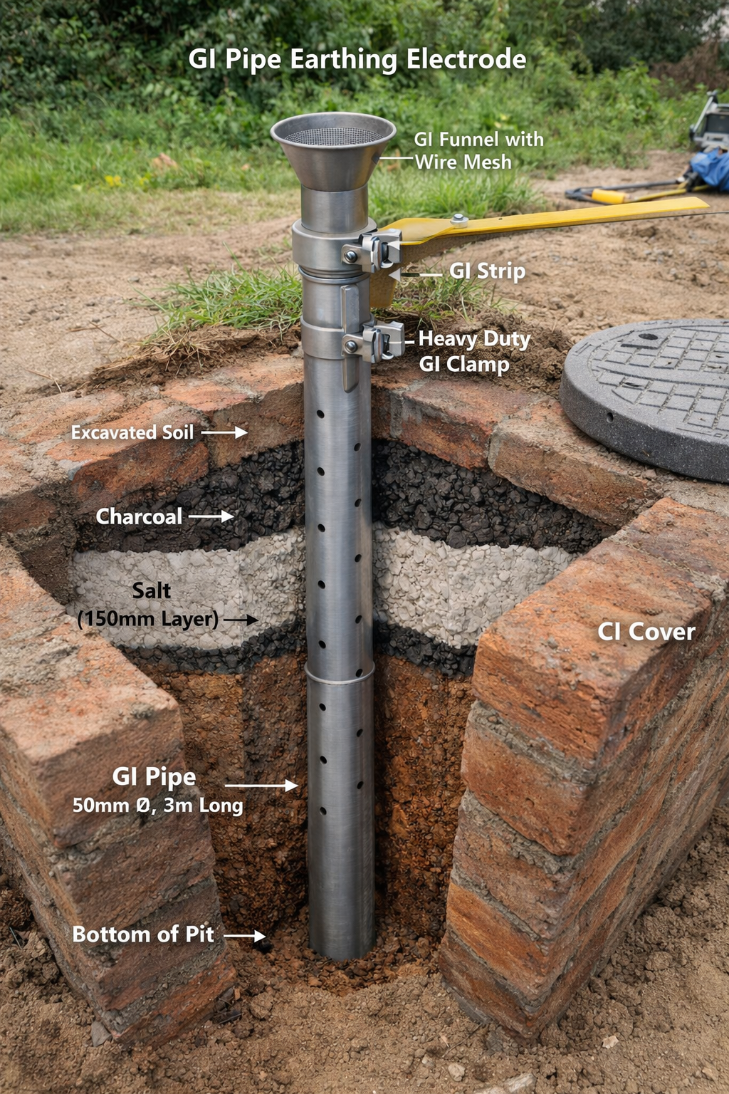
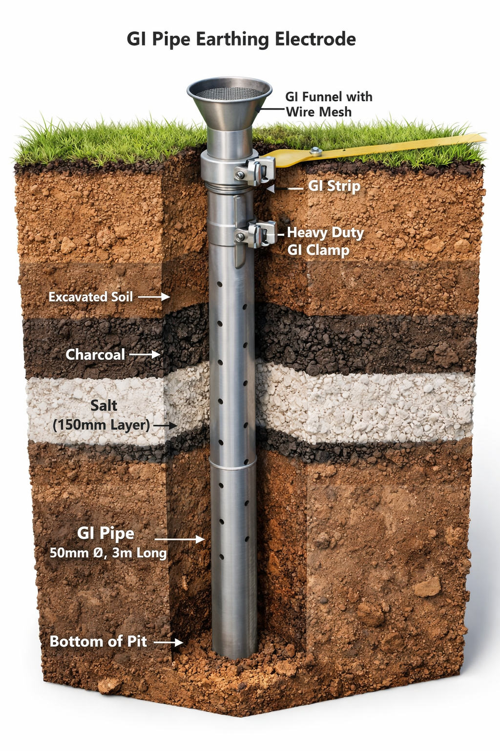
1. Pipe Earthing
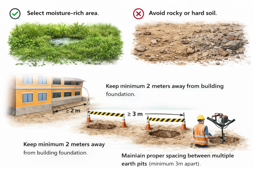
This is one of the most common and economical methods. A GI pipe is placed vertically into the ground and surrounded by charcoal and salt to reduce soil resistance.
It is widely used in residential and commercial buildings.
2. Plate Earthing
A copper or GI plate is buried deep in the soil. This method is suitable for higher load applications and industrial setups.
3. Rod Earthing
Copper-bonded rods are driven into the ground. This method is fast to install and requires less space.
4. Strip or Wire Earthing
Used in large installations like substations, where a network of conductors is buried underground.
Each method aims at achieving low earth resistance and stable grounding performance.
 |  |  |
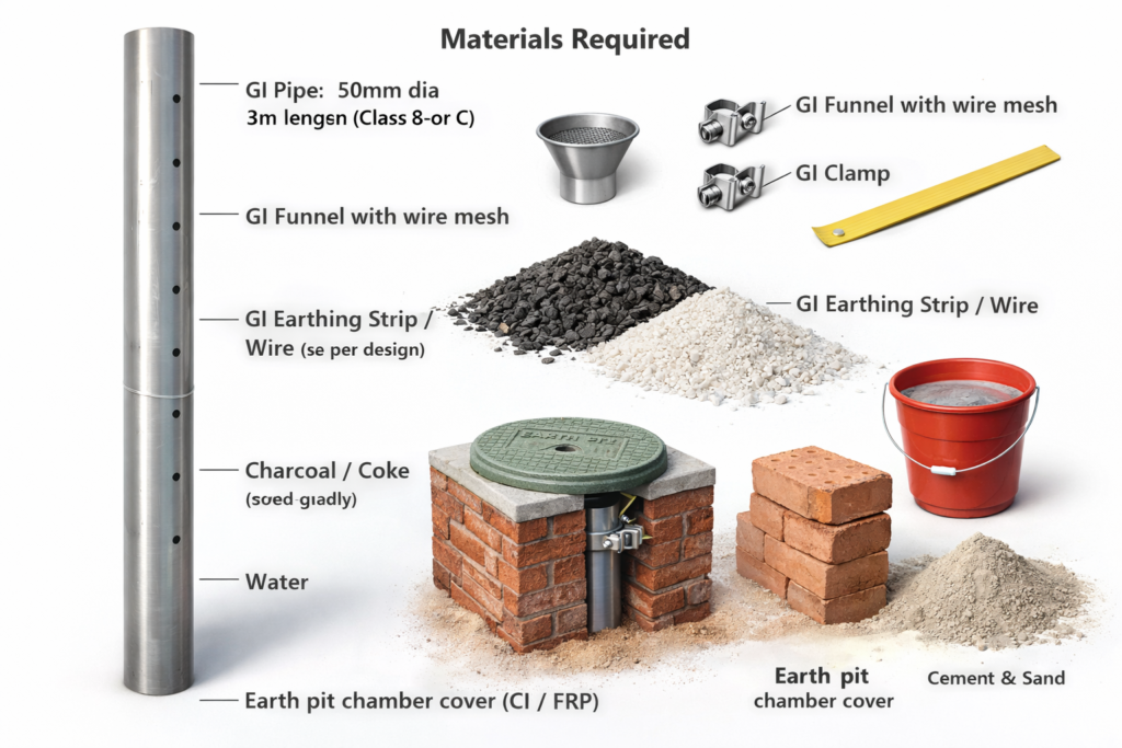
Materials Required During the Installation of GI Pipe Earthing
•GI Pipe – 50mm diameter, 3m length
(Class B or C)
•GI Funnel with wire mesh
•GI Clamp (Heavy Duty)
•GI Earthing Strip / Wire (as per design)
•Charcoal / Coke (good quality)
•Salt (industrial grade)
•Water
•Earth pit chamber cover (CI / FRP)
•Brick for chamber construction
- GI Pipe Earthing – 50mm Diameter, 3m Length (Class B or C)
This is the main earth electrode. It is installed vertically into the ground to create a low-resistance path for fault current. The 3-meter length helps reach moist soil layers for better conductivity. Class B or C indicates pipe thickness; thicker pipes provide higher mechanical strength and longer service life, especially in corrosive soil conditions. - GI Funnel with Wire Mesh
The funnel is fixed at the top of the pipe to allow watering of the earth pit. The wire mesh prevents stones, mud, and insects from entering the pipe and blocking it. - GI Clamp (Heavy Duty)
This clamp connects the earthing strip or wire securely to the GI pipe. A strong and tight connection ensures proper current flow during fault conditions. - GI Earthing Strip / Wire (As Per Design)
This conductor carries leakage or fault current from equipment to the earth electrode. The size is selected based on load and safety standards. - Charcoal / Coke (Good Quality)
Charcoal improves soil conductivity and helps maintain low earth resistance around the electrode. - Salt (Industrial Grade)
Salt absorbs moisture and increases the conductivity of the surrounding soil, improving earthing performance. - Water
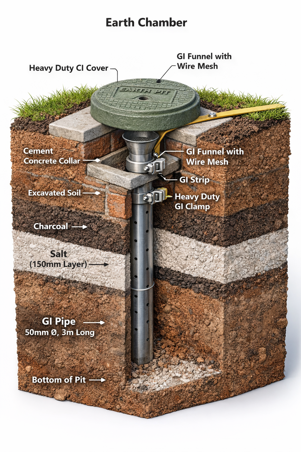
Water maintains moisture levels in the earth pit, especially during dry weather, ensuring consistent resistance values. - Earth Pit Chamber Cover (CI / FRP)
This cover protects the top of the electrode and allows easy inspection and testing. - Bricks for Chamber Construction GI pipe earthing
Bricks are used to construct the earthing chamber, providing structural support and protecting the installation.
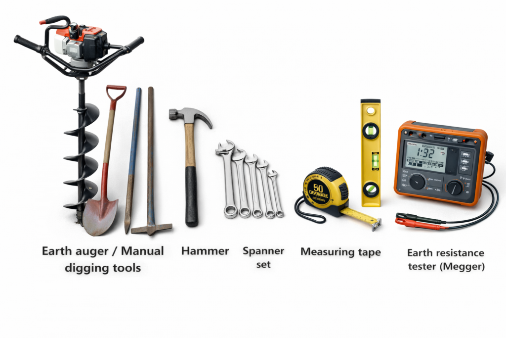
Tools Required (GI Pipe Earthing/Plate Earthing)
Earth auger / Manual digging tools
•Hammer
•Spanner set
•Measuring tape
•Spirit level
•Earth resistance tester (Megger)
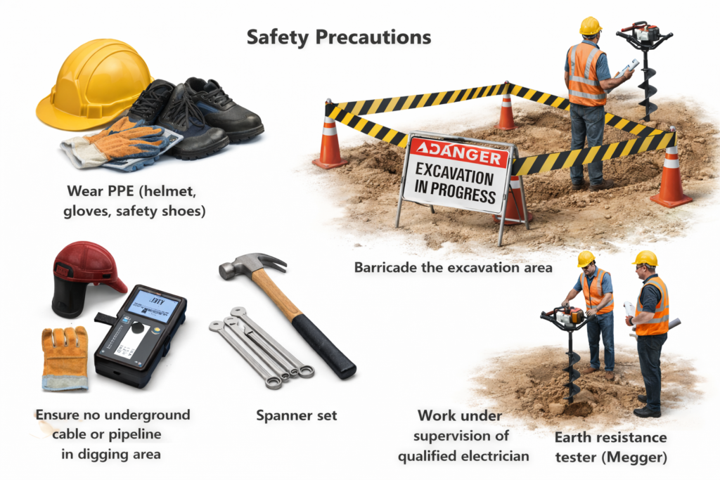
Safety Precautions (Gi Pipe Earthing / Plate Earthing)
- Wear PPE (helmet, gloves, safety shoes)
- Safety Precautions:
- Ensure no underground cable or
- pipeline in digging area.
- Barricade the excavation area.
- Work under supervision of
- qualified electrician
Safety Requirements and Precautions During GI Pipe Earthing Work
- Wear Proper PPE (Personal Protective Equipment)
All workers must wear safety helmet, insulated gloves, and safety shoes before starting excavation or installation work. The helmet protects from falling objects or accidental impact. Insulated gloves reduce the risk of electric shock during connection work. Safety shoes with hard toe and rubber sole protect against sharp objects, slipping, and accidental contact with live parts. PPE is not optional — it is the first level of protection on site. - Check for Underground Services Before Digging
Before starting excavation, confirm that there are no underground electrical cables, water pipelines, gas lines, or communication ducts in the digging area. Use approved drawings and, if required, a cable locator. Accidental damage to underground utilities can cause serious injury, service interruption, or fire hazards. - Barricade the Excavation Area
The excavation pit must be properly barricaded using caution tape, cones, or temporary fencing. This prevents accidental falls and ensures site safety for workers and the public. - Work Under Qualified Supervision
All earthing installation and electrical connections must be carried out under the supervision of a qualified electrician or electrical engineer to ensure correct installation and compliance with safety standards.
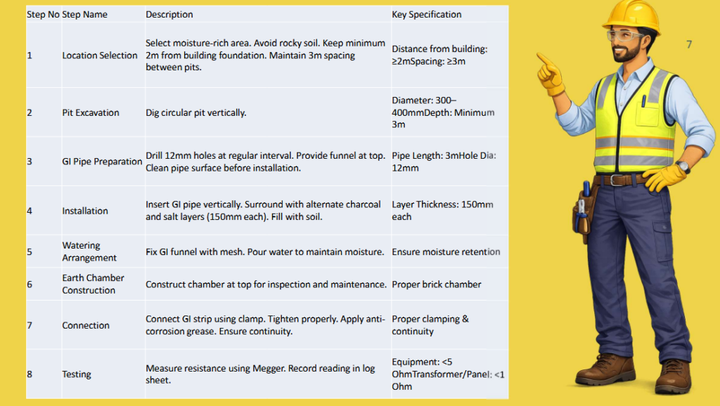
Procedure
Check Clearance before Earth pit excavation Gi pipe earthing / plate earthing
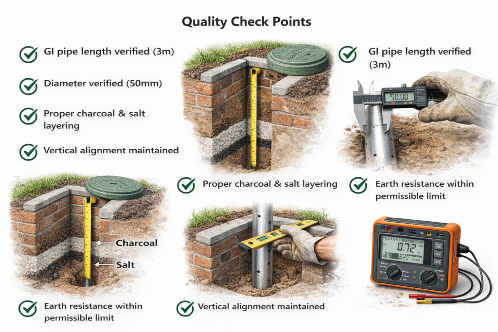
Quality Check Points GI pipe earthing
GI Pipe Length Verified (3m)
Before installation, confirm that the GI pipe length is exactly 3 meters as per design specification. Proper length is important because deeper installation helps reach moist soil layers, which improves conductivity and reduces earth resistance. If the pipe is shorter than specified, the grounding performance may not meet safety requirements.
Diameter Verified (50mm)
The pipe diameter must be checked to ensure it is 50mm as required. Correct diameter provides adequate surface area for current dissipation into the soil. A smaller diameter may reduce the efficiency of fault current discharge and affect long-term performance.
Proper Charcoal and Salt Layering
Charcoal and salt must be placed in alternate layers around the GI pipe. This improves soil conductivity and helps maintain moisture. Proper compaction of these layers is necessary to avoid air gaps, which can increase resistance.
Vertical Alignment Maintained
The electrode must be installed in proper vertical position. A tilted pipe may reduce effective contact with surrounding soil and affect uniform current distribution.
Earth Resistance Within Permissible Limit
After installation, earth resistance must be tested using an earth tester. The measured value should be within the acceptable limit as per project specification or electrical standards to ensure safe system performance.
Earthing in Different Applications
Earthing is not limited to buildings. It plays a critical role in many areas.
Residential Buildings
Protects occupants from electric shock and stabilizes voltage supply.
Commercial Complexes
Ensures safe operation of elevators, HVAC systems, and lighting networks.
Industrial Plants
Prevents equipment damage and ensures machinery safety.
Data Centers
Protects sensitive electronics from voltage fluctuations.
Solar Power Systems
Prevents damage from lightning and surge currents.
In modern infrastructure, earthing is not optional — it is mandatory.
GI Pipe Earthing and Lightning Protection
Lightning carries extremely high voltage. If a structure is not properly grounded, lightning strikes can cause severe structural and electrical damage.
Lightning protection systems work together with earthing. When lightning strikes, the energy is directed into the earth safely through conductors and electrodes.
Without earthing, lightning energy has no safe exit path.
Testing and Maintenance
Even the best earthing system needs regular inspection.
Earth Resistance Testing
An earth tester measures resistance periodically. If resistance increases beyond acceptable limits, corrective action is required.
Watering
In dry soil conditions, periodic watering helps maintain conductivity.
Visual Inspection
Check connections, clamps, and conductors for damage or corrosion.
Routine maintenance ensures continuous safety.
Common Mistakes in Gi pipe Earthing
Let’s be honest — many failures happen due to poor installation.
Common issues include:
- Shallow electrode installation
- Loose connections
- Using undersized conductors
- Ignoring soil resistivity
- No periodic testing
Cutting corners in earthing is risky. Safety should never be compromised.
Benefits of Proper GI Pipe Earthing
When done correctly, earthing provides:
- Protection against electric shock
- Fire prevention
- Equipment protection
- Voltage stabilization
- Lightning safety
- Regulatory compliance
It improves overall system reliability and reduces downtime.
Future of Earthing Systems
With growing infrastructure, renewable energy systems, and smart grids, earthing systems are becoming more advanced. (GI pipe Earthing)
Modern techniques include:
- Chemical earthing electrodes
- Maintenance-free earthing systems
- Deep-driven copper-bonded rods
- Integrated grounding networks
As technology evolves, the importance of earthing only increases.
Final Thoughts
GI Pipe Earthing may not be visible once installed, but its role is massive. It protects lives, machinery, and entire electrical networks.
Think of earthing as a silent guardian — always working in the background, ready to handle unexpected faults.
No electrical system is complete without proper grounding. Whether it’s a small house, a high-rise building, or a large industrial plant, earthing is the foundation of electrical safety.